Built-in Current, Voltage, Power, Time and Pulse monitor
Triple pulse weld profile
Pre-weld Check Process Tool
Set Monitor Hi/Low limits
Comprehensive Machine I/O
Communication Options
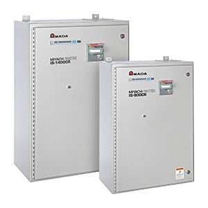
NEMA style enclosures
Applications
Automotive sheet metal and components
Stainless and galvanized doors and furniture
High-speed bi-metal contact welding
Storage Batteries
Aircraft components (aluminum and titanium)
Nut welding
Projection welds
Motor armature fusing
Markless welding
Heavy gauge shelving and wire welds
Copper wire fusing
Aluminum structure welds
Welding of advanced steels
Appliance sub-assemblies
Features
Closed loop technology : Inverters produce consistent, reliable welds with optimal nugget formation, superior joint strength and excellent surface appearance.
Fine heat input control : Short weld times and millisecond control provide more accurate welds, resulting in a smaller heat affected zone (HAZ), and facilitating longer electrode life than conventional AC welding technology. Markless welding also becomes possible.
Control mode flexibility : Select which mode fits the application, with fast rise times for conductive material or finer control for resistive material. Constant Power feedback mode helps to break up surface oxides and extends electrode life, especially when welding coated steels or aluminum.
Reduce operating costs : Inverters draw less energy from the incoming power line than single phase AC welders. This leads to greater cost savings and power efficiency in today’s modern manufacturing plants.
Automation-ready : Inverter transformers are smaller than AC transformers, making them well suited for automation and robotics.
Process control : The ISA’s stable welding control and built-in monitoring deliver wider process windows and traceability, and fulfill documentation requirements for many of today’s industries.
Improve weld reliability : Inverters have greatly reduced secondary inductive losses, which eliminate many welding problems associated with AC welding technology.
We use cookies to ensure that we give you the best experience on our website. If you continue to use this site we will assume that you are happy with it.